Theory and Background
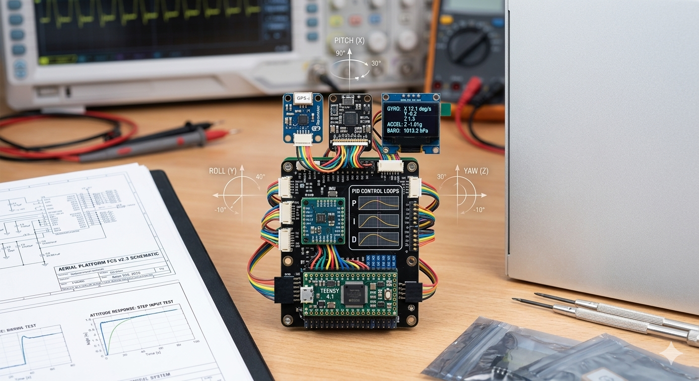
Concept view of the embedded flight stack: Teensy controller, sensor interfaces, and the roll, pitch, and yaw control loops this theory section explains.
Quadcopter dynamics
A quadcopter is an under-actuated rigid body with six degrees of freedom and four independent actuators. The motors generate thrust forces and reaction torques that combine into net force and net moment on the vehicle.
Coordinate frame
The body frame is defined with:
- X pointing forward
- Y pointing left
- Z pointing up
Roll is rotation about X, pitch about Y, and yaw about Z. The world frame may be modeled with either NED or ENU conventions depending on the analysis workflow.
Equations of motion
- Linear: total force equals mass times acceleration
- Rotational: torque equals rigid-body inertia effects plus angular-rate coupling
These dynamics are the basis for simulation, controller design, and validation.
PID control background
The initial controller is cascaded PID. Each controller combines:
- proportional action for immediate error correction
- integral action to reduce steady-state bias
- derivative action to damp response and reduce overshoot
For the quadcopter, outer-loop objectives generate attitude or thrust targets, while inner loops track those targets using sensor feedback.
Attitude estimation
Raw accelerometer and gyroscope data are fused with a complementary filter:
angle = alpha * (angle + gyro_rate * dt) + (1 - alpha) * accel_angle
At the current target loop rate, an alpha value around 0.98 is a reasonable starting point for blending short-term gyro stability with long-term accelerometer reference.
Why theory matters here
This project is not only about making the vehicle fly. It is also a platform for:
- learning control theory by implementation
- validating models against real hardware
- building reusable documentation for future teams
- creating a path toward LQR, MPC, and adaptive control methods